Modelling Conduction with Internal Heat Generation
In this article, we will analyse the heat transfer of a composite material wall with internal heat generation from one of its materials.
The original problem sourced from an online lecture on heat transfer [video link here, please note that you will be leaving our website. We are not responsible for the content or safety of external sites.] by Dr. Ethan Languri, is modelled using HeatCond2D to compare its numerical solution against the established analytical solution.
Problem Definition and Assumptions
The wall geometry and boundary conditions are illustrated in the diagram below.
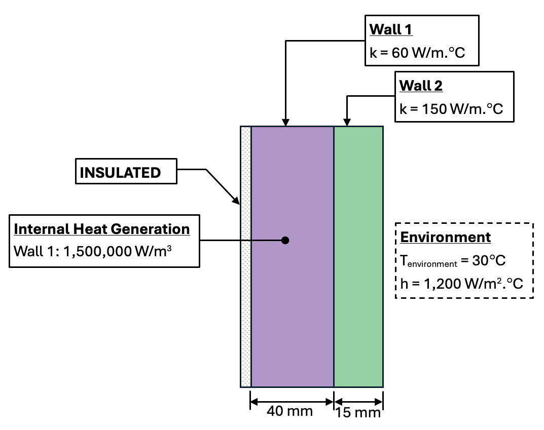
Sketch
Wall Arrangement
Based on the physical arrangement, heating and exposure conditions, the heat transfer process can modelled as steady-state and one-dimensional under the following assumptions:
Uniform Convection: Convective heat transfer is applied uniformly on Wall 2 external surface.
One-Dimensional Flow: Temperature gradients and heat flux in the vertical and depth directions are negligible.
Steady-State Conditions: The system represents long-term, steady-state heat loss per unit area after initial transient effects have dissipated.
[Tips & Tricks: If the insulation layer has a lower thermal conductivity relative to the other wall materials, the heat flux penetrating through the insulation to the external environment is assumed to be negligible. Consequently, the unexposed outer surface of the insulation layer is modelled using an adiabatic boundary condition instead of a physical material.]
Numerical Procedure and Results
(Detailed modelling steps are provided at the end of this article.)
Following the analysis using HeatCond2D, the surface temperature of the non-insulated side is evacuated on the Results Page of the app:
Wall 2 Surface Temperature: 80.0°C
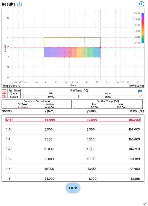
HeatCond2D Results Page
Temperature at surface of Wall 2
The analytical solution from the online lecture gives a Wall 2 surface temperature of 80.0°C, which perfectly aligns with the surface temperature estimated from HeatCond2D.
A section temperature slice from HeatCond2D (shown below) can be viewed in HeatCond2D.
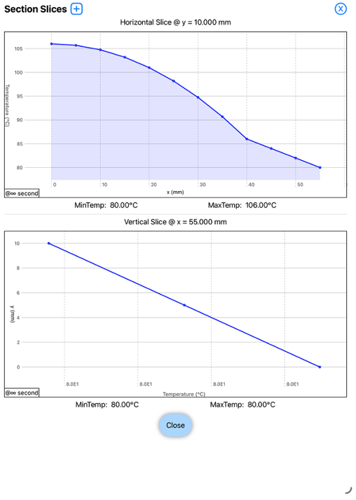
HeatCond2D Results Page
Section Temperature Slice
The .txt input file for the HeatCond2D model is available for download here.
If you have any queries or feedback regarding this article, please contact us.
If you wish to download HeatCond2D, click here.
Step-by-Step Heat Transfer Analysis
We will begin by creating a section of the wall including the two materials.
Open the HeatCond2D app and tap on the Section Page. Tap <Solid> to ensure that the Solid Element is selected. We will treat Wall 1 as the Solid Element.
Next tap on the Section Template button to access the Section Template Page.
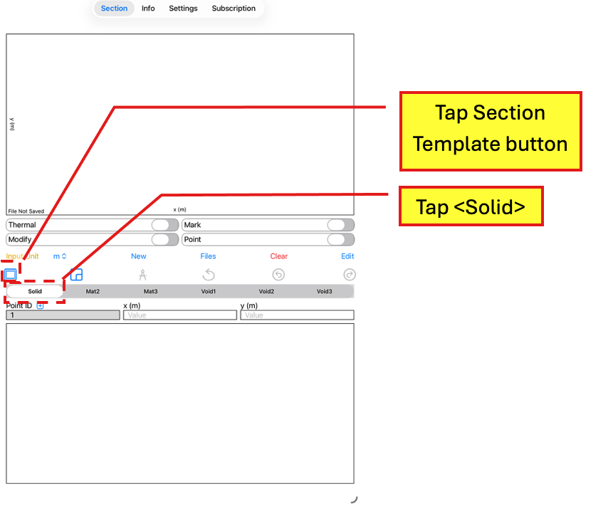
Section Page
Tap <Solid>
Tap Section Template button
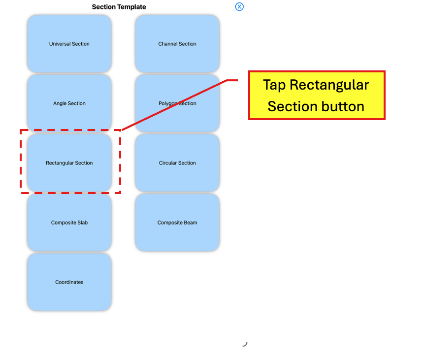
In the Section Template Page, tap on the Rectangular Section button. This action will bring up a template for a rectangular section.
Section Template
Tap Rectangular Section button
Under Input Unit, select mm to change the unit.
Then, enter the following dimensions:
b0 = 55 in mm
d0 = 20 in mm
leave b1 and d1 empty.
[Tips & Tricks: For a 1D problem, select a value for d0 based on the minimum 2 meshes. As we will apply symmetry modelling later on, we define d0 as 4 meshes with a vertical mesh size of 5 mm equivalent to the horizontal mesh size. which gives a total depth of 20 mm.]
Ensure that the Outer Element and Inner Element are set to Solid and Void1 respectively.
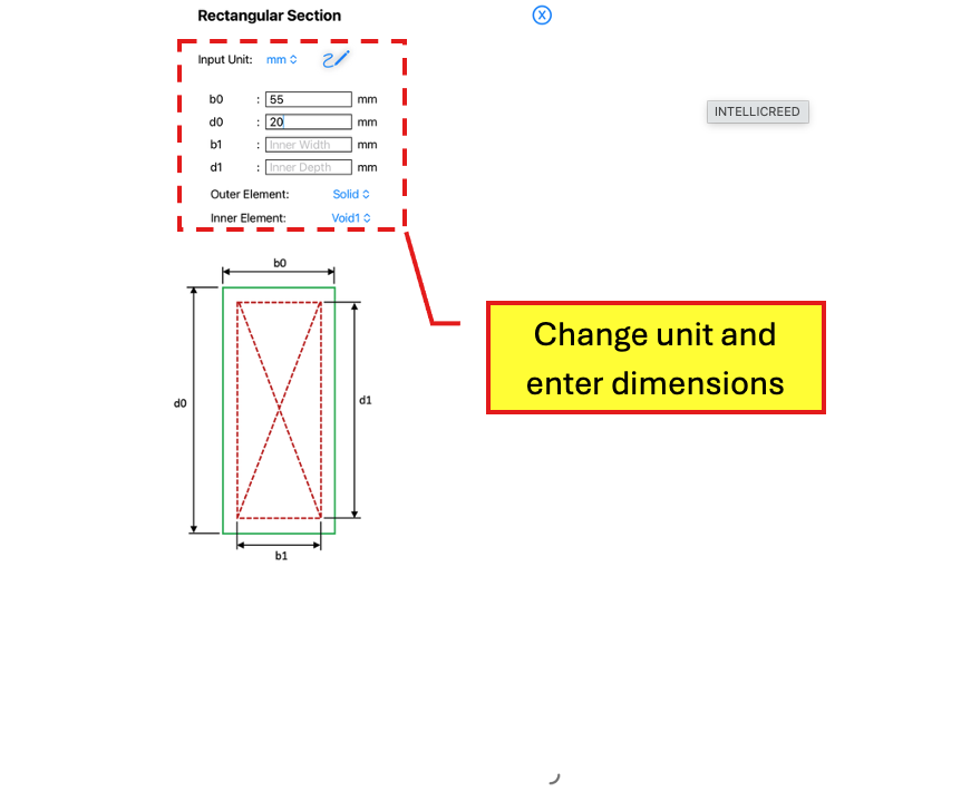
Rectangular Section (Template)
Change unit and enter dimensions
Tap on the Scribble button to create the rectangular section.
Back in the Section Page, tap on <Mat2> which will be used for Wall 2.
Tap on the Section Template button to access the Shape Template Page.
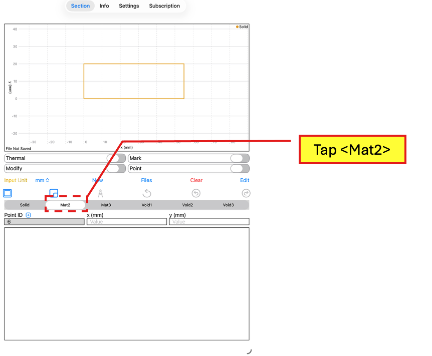
Section Page
Tap <Mat4>
Tap Shape Template button
Select <Rectangle> and enter the following information:
cx = 47.5 in mm
cy = 10 in mm
leave t as empty
b0 = 15 in mm
d0 = 20 in mm
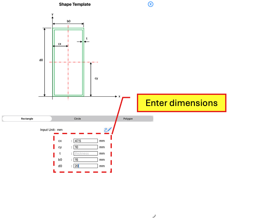
Shape Template
Tap <Rectangle>
Enter dimensions
Tap on the Scribble button to create the rectangle and return to the Section Page.
The next step is to create the heat transfer model. In the Section Page, toggle on the Thermal toggle button to access the Thermal Page.
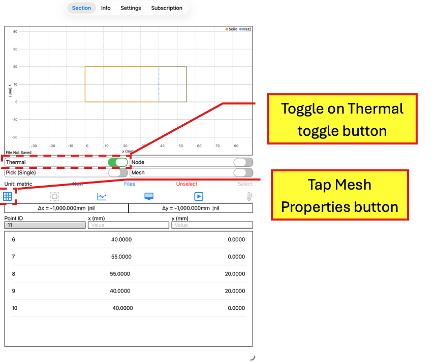
Section Page -> Thermal Page
Toggle on Thermal toggle button
Tap Mesh Properties button
We will then generate the meshes for the model. Tap on the Mesh Properties button to access the Mesh Properties Page.
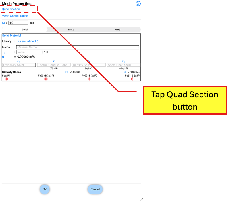
Mesh Properties Page
Tap Quad Section button
Tap on the Quad Section button to access the Quad Section Page. In the Quad Section Page, tap the “SouthWest Corner“ and “SouthEast Corner“ buttons.
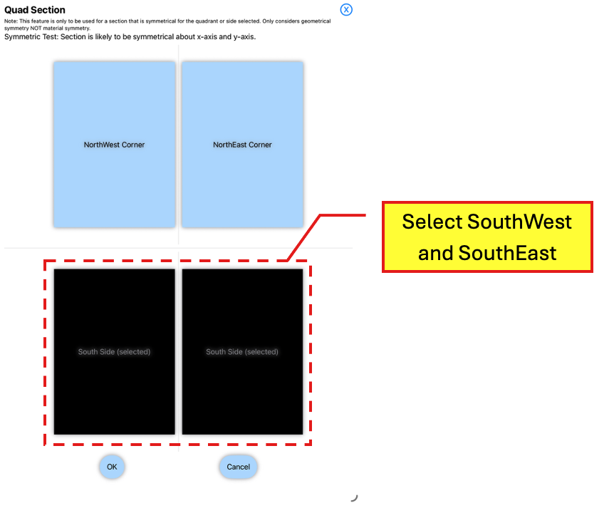
Quad Section Page
Tap SouthWest and SouthEast buttons
Tap on the OK button to return to the Mesh Properties Page.
In the Mesh Properties Page, tap on the Mesh Configuration button to access the Mesh Configuration button.
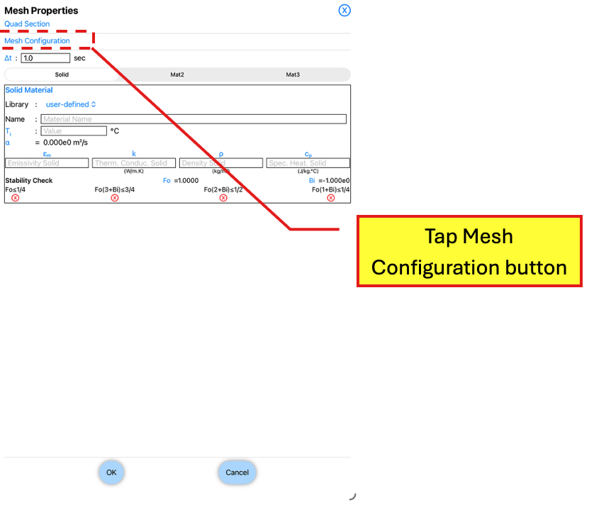
Mesh Properties Page
Tap Mesh Configuration button
Enter Δx of 5 in mm and Δy of 5 in mm. Leave Mesh Symmetry as “About y- and x- axes and Selected Mesh Size as “Modified Mesh Size”.
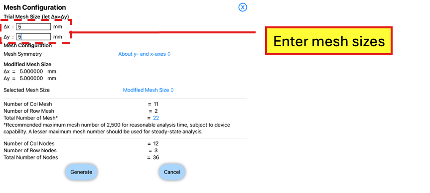
Mesh Configuration Page
Enter mesh sizes
Tap the Generate button to return to the Mesh Properties Page.
In the Mesh Properties Page, select <Solid> and enter the following information:
Name: Wall 1
Ti: 1
εm: 1
k: 60 in W/m.K
ρ: 1
cp: 1
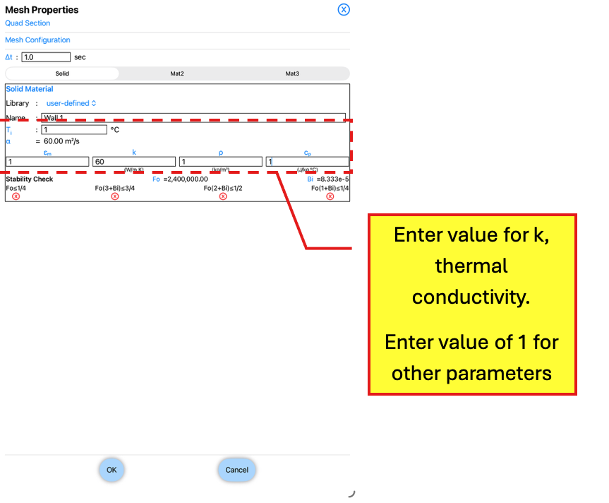
Mesh Properties Page
Under <Solid>, enter value for k and 1 for the other parameters
Next, select <Mat2> and enter the following information:
Name: Wall 2
Ti: 1
εm: 1
k: 150 in W/m.K
ρ: 1
cp: 1
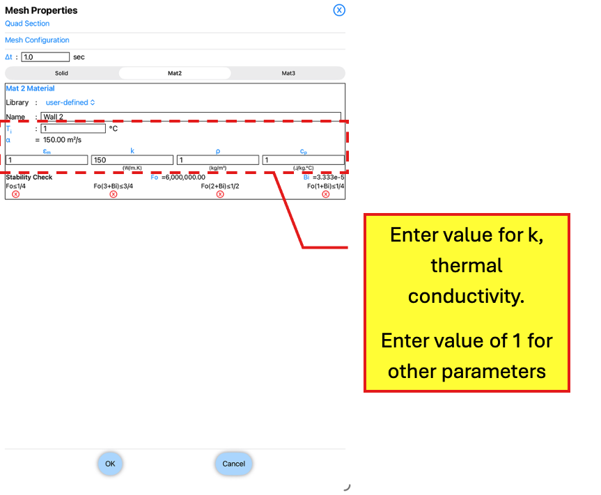
Mesh Properties Page
Under <Mat2>, enter value for k and 1 for other parameters
Tap the OK button to return to the Thermal Page.
We will then apply the boundary condition and internal heat generation to the nodes.
Double tap on the gold Node (Ext) text of the toggle button to change it to Node (All), which will show the internal nodes.
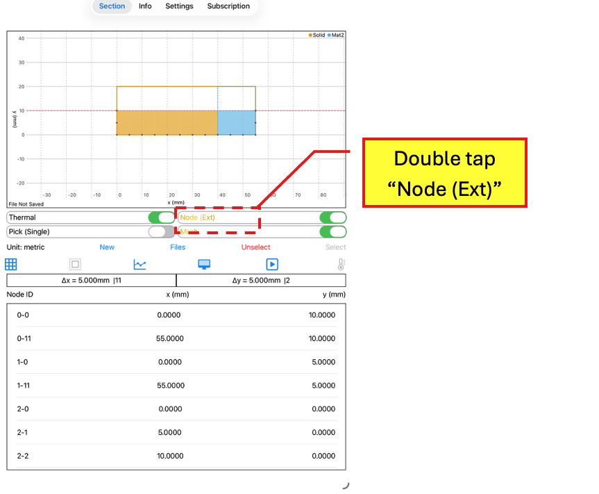
Thermal Page (Thermal Toggle button On)
Whatever it is, the way you tell your story online can make all the difference.
Next, toggle on the Pick (Single) toggle button to Pick (Group).
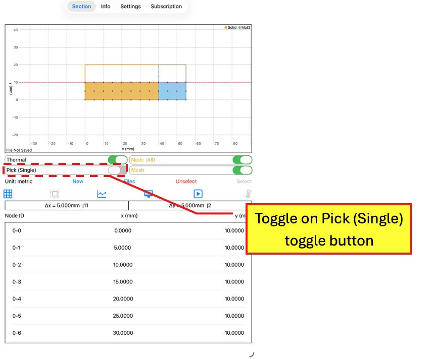
Thermal Page (Thermal Page button On)
Toggle on Pick (Single) toggle button
Tap around the Wall 1 nodes to create a band. Tap Select to close the band. The selected nodes will be highlighted.
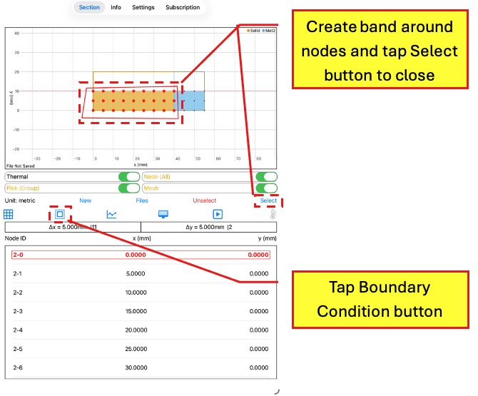
Thermal Page (Thermal Page button On)
Create band around Wall 1 nodes
Tap Boundary Condition button
Tap the Boundary Condition button to access the Node Boundary Conditions Page. Enter the following information under “Exposure Type: Internal Heat”:
Int. Heat Generation: 1500000 in W/m³
Node Boundary Conditions Page
Enter value for Int. Heat Generation
Note that only internal heat generation can be specified for the internal nodes of Wall 1.
Tap Unselect to unselect the highlighted nodes.
Next, tap around the internal nodes between Wall 1 and Wall 2 to create a band.
Tap the Boundary Condition button to access the Node Boundary Conditions Page.
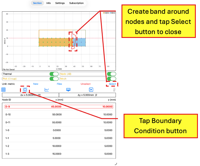
Thermal Page (Thermal Page button On)
Create a band around the nodes at the interface between Wall 1 and Wall 2
Tap Boundary Condition button
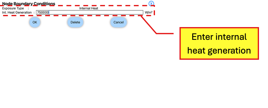
Enter the following information under “Exposure Type: Internal Heat”:
Int. Heat Generation: 750000 in W/m³
[Notes: These internal nodes are located between two materials and as only one material is generating internal heat, the internal heat generation at these nodes is half the internal heat generation of the wall. We will provide another example soon where the internal heat generation is generated at the external nodes.]
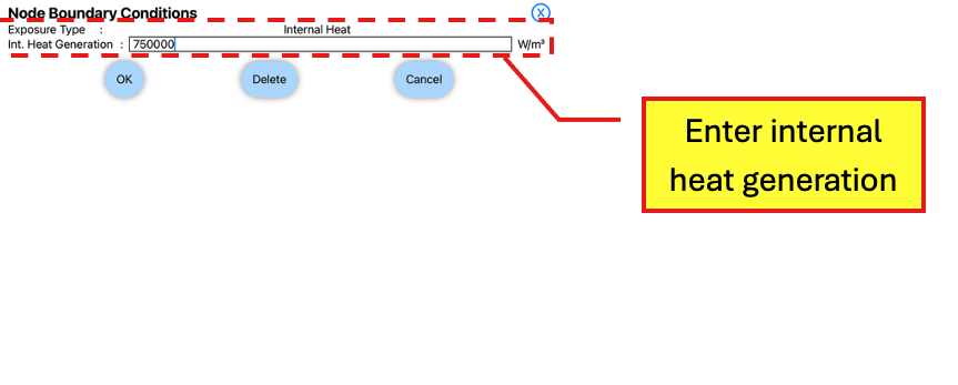
Node Boundary Conditions Page
Enter value for Int. Heat Generation
Double tap the gold Node (All) text of the toggle button to change it to Node (Ext), which will hide the internal nodes.
Tap around the Wall 2 external nodes to create a band. Tap Select to close the band. The selected nodes will be highlighted,
Next, tap the Boundary Condition button to access the Node Boundary Conditions Page.
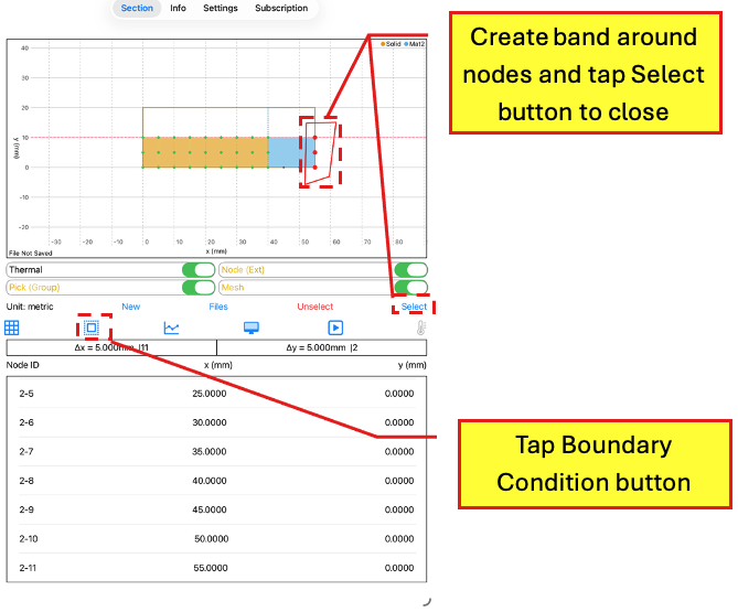
Thermal Page (Thermal Page button On)
Create a band around the Wall 2 external nodes
Tap Boundary Condition button
Enter the following information:
Select “Surface Temp.” as the Exposure Type
Select “Constant Temp." as the Temp. Type
Constant Temp.: 30.0°C
Tap Convective (Transient Gain/SteadyState) and enter h = 1,200 W/m².K
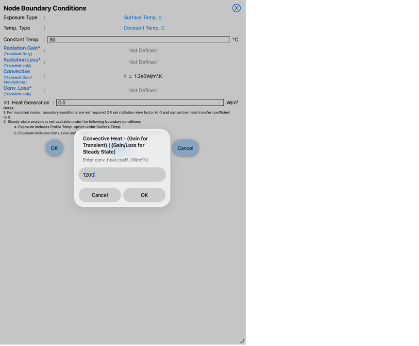
Node Boundary Conditions
Enter values for Constant Temp. and Convective (Transient/SteadyState) for the Wall 2 external nodes
Tap the OK button to return to the Thermal Page.
[Warning: When running a steady-state analysis, note that only one value can be entered for the convective heat transfer coefficient unlike a transient analysis where convective gain and convective loss can have separate values.]
In the Thermal Page, tap an external node to view the node data.
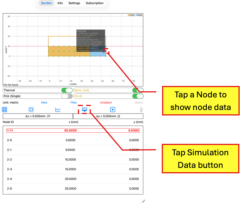
Thermal Page (Thermal Toggle button On)
Tap a Node to show node data
Tap Simulation Data button
Next, tap the Simulation Data button to access the Simulation Data Page.
In the Simulation Data Page, select <Steady-State> and <Gauss-Seidel>. Tap the OK button to return to the Thermal Page.
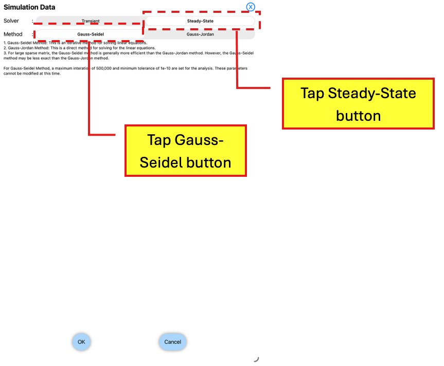
Simulation Data Page
Tap <Steady-State>
Tap <Gauss-Seidel>
In the Thermal Page, tap the Run button to run the heat transfer analysis.
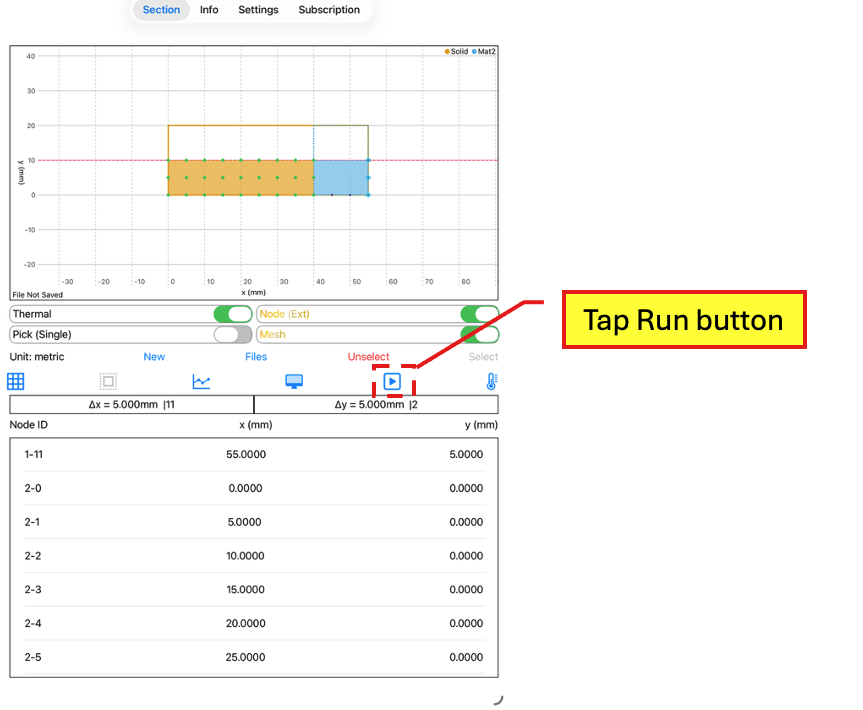
Thermal Page (Thermal Toggle button On)
Tap Run button
A dialog box will appear. Tap the OK button to continue with the analysis.
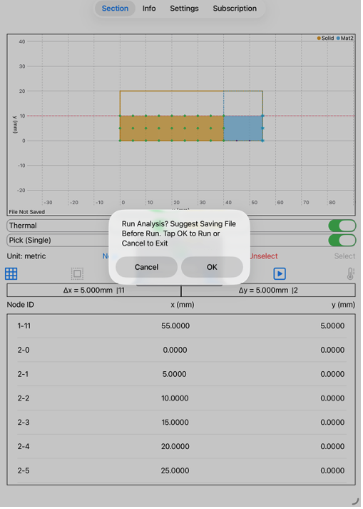
Thermal Page (Thermal Toggle button On)
Tap OK to run analysis when dialog box appears
The Results Page will automatically appear after the analysis has been completed.

Results Page
View Results